PicoSource AS108 Overview
Professional and portable performance at low cost
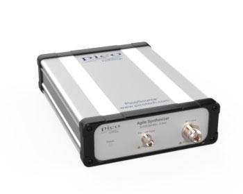
The PicoSource™ AS108 Agile Synthesizer generates signals to meet the needs of both benchtop and integrated module applications. Its broad 300 kHz to 8 GHz frequency range, fast settling and programmable phase, frequency and amplitude match it to a wide range of applications, with the added advantages of low cost, small footprint and 12 to 15 V power requirement.
The AS108 has professional-grade performance that is effective in both static and parameter-agile applications, making it a bench or field instrument for developers, scientists, educators, students, and service and installation technicians. Its speed, external clock referencing, trigger capabilities and user-programmable power-up mode all suit it to system integrations such as automated test, unmanned installations and multi-signal stimulus.
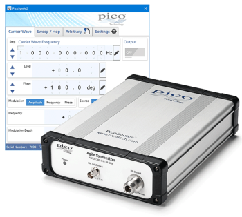
The AS108 is a full-function USB-controlled vector (IQ) modulating signal synthesizer. It is supplied with a clean, easy and efficient user interface for controlling its amplitude, frequency and phase agility; including modulations, sweeps, hopping and list modes from Microsoft Windows. Multiple synthesizers can be controlled from multiple instances of the software running on a single controlling PC or device. Remote control is also possible using the API included.
| General | ||
|---|---|---|
| Standard conditions are ambient temperature between 15°C and 30°C, 20 minutes after power-up. |
| Carrier wave | ||||||||||||||
|---|---|---|---|---|---|---|---|---|---|---|---|---|---|---|
| Parameter | Applicable range and values | Condition | ||||||||||||
| Frequency range | 300 kHz to 8.192 GHz | |||||||||||||
| Frequency resolution |
|
|||||||||||||
| Frequency settling time |
|
to ±10 ppm | ||||||||||||
| Frequency accuracy (internal reference) | ±5 ppm | |||||||||||||
| Output power range | −15 dBm to +15 dBm | |||||||||||||
| Output power resolution | 0.1 dBm | |||||||||||||
| Output power setting accuracy | ±1.5 dB | |||||||||||||
| Output match (VSWR) |
|
|||||||||||||
| Output amplitude settling time |
|
|||||||||||||
| Output protection | 25 V DC pk and 20 dBm | |||||||||||||
| Phase noise at 10 kHz offset |
|
|||||||||||||
 |
Measured phase noise at 1 GHz | |||||||||||||
| Harmonics |
|
Output power set to +10 dBm | ||||||||||||
| Sub-harmonics |
|
Output power set to +10 dBm | ||||||||||||
| Spurious |
|
Output power set to +10 dBm | ||||||||||||
| Sweep, hop and list modes | ||
|---|---|---|
| Parameter | Applicable range and values | Condition |
| Sweep, hop or list parameters | Frequency; level; phase; frequency and level; phase and level | |
| Discrete sweep or list points | 2 to 10 001 (or 2 to 1750 points when saving power-up settings to device) | Hop is a special case of sweep with only two points. |
| Frequency stepping dwell time | 27 to 65 500 µs (or 27 µs to 1750 µs when saving power-up settings to device) | Excepting any step exceeding ±2.2 GHz to or from the frequency band 7.0 GHz to 8.0 GHz, minimum dwell 100 µs. |
| Modulation | ||||||||
|---|---|---|---|---|---|---|---|---|
| Parameter | Applicable range and values | Condition | ||||||
| Frequency range internal sine source | 10 Hz to 5 kHz | |||||||
| Internal modulation sample rate | 37 kS/s | Sampled sideband spurs are generated at 37 kHz offset. At 1 kHz modulation typically < -30 dB relative to sidebands. | ||||||
| Frequency resolution and accuracy | 1 Hz resolution ± 0.1% accuracy | |||||||
| AM depth range |
|
|||||||
| FM deviation | 2% carrier frequency or 200 kHz maximum | |||||||
| PM deviation | ±180° | |||||||
| External modulation input bandwidth | DC coupled to 10 kHz | |||||||
| External modulation input sampling | AM: 125 kS/s FM/PM: 89 kS/s at 12-bit resolution |
Sampled sideband spurs are generated at 125 / 89 kHz offset. At 1 kHz modulation typically < -50 dB relative to sidebands. | ||||||
| External modulation input sensitivity |
|
for selected depth or deviation | ||||||
| External modulation input protection | ±5 V DC + AC pk | |||||||
| Synchronization I/O | |||||||
|---|---|---|---|---|---|---|---|
| Internal 10 MHz reference output |
|
Into 50 Ω | |||||
| External reference input |
|
||||||
| External reference lock range |
|
||||||
| Trigger input threshold voltage |
|
||||||
| Trigger output logic levels |
|
Into 1 kΩ Into 50 Ω |
|||||
| Trigger output rise and fall times |
|
Into 50 Ω | |||||
| Trigger in to trigger out delay |
|
Gives a lead of 17.5 µs to frequency / phase step, 37.5 µs to a level step. | |||||
| Trigger out to triggered event delay | 17.5 µs typical | Frequency or phase step | |||||
| 37.5 µs typical | Level step | ||||||
| Dwell period holds off (prevents receipt of) a further trigger. | |||||||
| Trigger input protection | ±10 V DC + AC peak | ||||||
| Trigger output protection | ±4 V DC + AC peak | ||||||
| Reference I/O protection | 4 V AC p-p ±15 V DC | ||||||
| Miscellaneous and environmental specifications | ||
|---|---|---|
| Power requirements | +12 V to +15 V DC, 12 W, 2.1 mm jack, centre pin positive | |
| Control interface | USB 2.0 | |
| Dimensions | W 173 mm x L 232 mm x H 56 mm | Excluding connectors |
| Weight | 1.78 kg | |
| Operating environment | +5°C to +40°C, 80% RH non-condensing, Pollution Degree 2 | |
| Storage environment | −20°C to +50°C, 80% RH non-condensing, Pollution Degree 2 | |
| Vibration tolerance | 0.5 g | 5 Hz to 300 Hz |
| Safety | Declared conforming to: EN61010-1:2010 and EN61010-2-030:2010 Safety requirements for electrical equipment for measurement, control and laboratory use, general requirements and for testing and measuring circuits. |
|
| EMC | Declared conforming to: EN61326-1:2013 Electrical equipment for measurement, control and laboratory use – EMC requirements. Group 1, Class B. (Emissions) EN61326-1:2013 Electrical equipment for measurement, control and laboratory use – EMC requirements. Basic Environment. (Immunity) EN61326-2-1:2013 Part 2-1: Test configurations, operational conditions and performance criteria for sensitive test and measurement equipment for unprotected applications. CFR 47 Code of Federal Regulations FCC: part 15 Subpart B – Frequency devices – unintentional radiators. Radiated emissions standard. Class A. |
|
| Warranty | 3 years | |
| ECCN coding | EAR99 | |


