
PicoScope 9300 Series
USB Sampling Oscilloscopes
With up to 25 GHz bandwidth, the PicoScope 9300 sampling oscilloscopes address digital and telecommunications applications of 10 Gb/s and higher, microwave applications up to 25 GHz and timing applications with a resolution down to 64 fs. Optional 11.3 Gb/s clock recovery, optical to electrical converter or differential, deskewable time domain reflectometry sources (60 ps/7 V) complete a powerful, small-footprint and cost-effective measurement package.
Sampling Oscilloscopes to 25 GHz with TDR/TDT and Optical models
15 to 25 GHz electrical, 9.5 GHz optical, TDR/TDT, 2-channel and 4-channel, compact, portable, USB instruments.
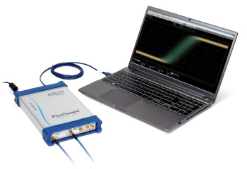
These units occupy very little space on your workbench and are small enough to carry with your laptop for on-site testing, but that’s not all. Instead of using remote probe heads attached to a large bench-top unit, you can position the scope right next to the device under test. Now all that lies between your scope and the DUT is a short, low-loss coaxial cable. Everything you need is built into the oscilloscope, with no expensive hardware or software add-ons to worry about.
Key specifications
- 15 TS/s (64 fs) sequential sampling
- Up to 15 GHz prescaled, 2.5 GHz direct trigger and 11.3 Gb/s clock recovery
- Industry-leading 16-bit 1 MS/s ADC and 60 dB dynamic range
- Eye and mask testing to 16 Gb/s with up to 223–1 pattern lock
- Intuitive, touch-compatible Windows user interface
- Comprehensive built-in measurements, histogramming and editable data mask library
- Integrated, differential, deskewable TDR/TDT step generator
Typical applications
- Telecom and radar test, service and manufacturing
- Optical fiber, transceiver and laser testing
- RF, microwave and gigabit digital system measurements
- Radar bands I, G, P, L, S, C, X, Ku
- Precision timing and phase analysis
- Digital system design and characterization
- Eye diagram, mask and limits test to 10 Gb/s
- Ethernet, HDMI 1, HDMI 2, PCI, SATA, USB 2.0, USB 3.0
- TDR/TDT analysis of cables, connectors, backplanes, PCBs and networks
- Optical fiber, transceiver and laser test
- Semiconductor characterization
Remember: the price you pay for your PicoScope Sampling Oscilloscope is the price you pay for everything – we don’t charge you for software features or updates.
Comparison with the PicoScope 9400 Series SXRTOs
Find out whether a PicoScope 9300 Sampling Scope or a PicoScope 9400 Sampler-Extended Real-Time Scope is best for your application. See a comparison table.
Migrating from the legacy PicoScope 9200 to the PicoScope 9300?
Help me compare
The now broader range of 9300 models and bandwidths is designed to offer high compatibility and upgraded functionality to replace the successful but now obsolete 9200 series of 12 GHz sampling oscilloscopes. A detailed intercomparison and assistance to migration is provided here:
| Oscilloscope – vertical (analog) | 9300-15 models | 9300-20 models | 9300-25 models |
|---|---|---|---|
| Number of channels | PicoScope 9341: 4 All other models: 2 |
||
| Acquisition timing | Selectable simultaneous or alternate acquisition | ||
| Bandwidth, Full | 15 GHz | 20 GHz | 25 GHz |
| Bandwidth, Narrow | 8 GHz | 10 GHz | 12 GHz |
| Pulse response rise time, full bandwidth | 23.4 ps (10% to 90%, calculated) | 17.5 ps (10% to 90%, calculated) | 14.0 ps (10% to 90%, calculated) |
| Pulse response rise time, narrow bandwidth | 43.8 ps (10% to 90%, calculated) | 35.0 ps (10% to 90%, calculated) | 29.2 ps (10% to 90%, calculated) |
| Noise, full bandwidth | < 1.2 mV RMS typical, < 1.6 mV RMS maximum | < 1.5 mV RMS typical, < 2.0 mV RMS maximum | < 1.9 mV RMS typical, < 2.5 mV RMS maximum |
| Noise, narrow bandwidth | < 0.7 mV RMS typical, < 0.9 mV RMS maximum | < 0.8 mV RMS typical, < 1.1 mV RMS maximum | < 1.0 mV RMS typical, < 1.3 mV RMS maximum |
| Noise with averaging | 100 μV RMS system limit, typical | ||
| Operating input voltage with digital feedback | 1 V p-p with ±1 V range (single-valued) | ||
| Operating input voltage without digital feedback | ±400 mV relative to channel offset (multi-valued) | ||
| Sensitivity | 1 mV/div to 500 mV/div in 1-2-5 sequence with 0.5% fine increments | ||
| Resolution | 16 bits, 40 μV/LSB | ||
| Accuracy | ±2% of full scale ±2 mV over nominal temperature range (assuming temperature-related calibrations are performed) | ||
| Nominal input impedance | (50 ±1) Ω | ||
| Input connectors | 2.92 mm (K) female, compatible with SMA and PC3.5 | ||
| Timebase (Sequential time sampling mode) | |
|---|---|
| Ranges | 5 ps/div to 3.2 ms/div (main, intensified, delayed, or dual delayed) |
| Delta time interval accuracy | For > 200 ps/div: ±0.2% of delta time interval ± 12 ps For < 200 ps/div: ±5% of delta time interval ± 5 ps |
| Time interval resolution | 64 fs |
| Channel deskew | 1 ps resolution, 100 ns max. |
| Triggers | |||
|---|---|---|---|
| Trigger sources | All models: external direct, external prescaled, internal direct and internal clock triggers. PicoScope 9302 and 9321 only: external clock recovery trigger |
||
| External direct trigger bandwidth and sensitivity | DC to 100 MHz : 100 mV p-p; to 2.5 GHz: 200 mV p-p | ||
| External direct trigger jitter | 1.8 ps RMS (typ.) or 2.0 ps RMS (max.) + 20 ppm of delay setting | ||
| Internal direct trigger bandwidth and sensitivity | DC to 10 MHz: 100 mV p-p; to 100 MHz: 400 mV p-p (channels 1 and 2 only) | ||
| Internal direct trigger jitter | 25 ps RMS (typ.) or 30 ps RMS (max.) + 20 ppm of delay setting (channels 1 and 2 only) | ||
| External prescaled trigger bandwidth and sensitivity | 1 to 14 GHz, 200 mV p-p to 2 V p-p | 1 to 14 GHz, 200 mV p-p to 2 V p-p 14 to 15 GHz, 500 mV p-p to 2 V p-p |
|
| External prescaled trigger jitter | 1.8 ps RMS (typ.) or 2.0 ps RMS (max.) + 20 ppm of delay setting | ||
| Pattern sync trigger clock frequency | 10 MHz to 14 GHz | 10 MHz to 14 GHz | 10 MHz to 15 GHz |
| Pattern sync trigger pattern length | 7 to 8 388 607 (223− 1) | ||
| Clock recovery (PicoScope 9302 and 9321) | |
|---|---|
| Clock recovery trigger data rate and sensitivity | 6.5 Mb/s to 100 Mb/s: 100 mV p-p >100 Mb/s to 11.3 Gb/s: 20 mV p-p |
| Recovered clock trigger jitter | 1 ps (typ.) or 1.5 ps (max.) + 1.0% of unit interval |
| Maximum safe trigger input voltage | ±2 V (DC + peak AC) |
| Input characteristics | 50 Ω, AC coupled |
| Input connector | SMA (F) |
| Acquisition | |
|---|---|
| ADC resolution | 16 bits |
| Digitizing rate with digital feedback (single-valued) | DC to 1 MHz |
| Digitizing rate without digital feedback (multi-valued) | DC to 40 kHz |
| Acquisition modes | Sample (normal), average, envelope |
| Data record length | 32 to 32 768 points (single channel) in x2 sequence |
| Display | |
|---|---|
| Styles | Dots, vectors, persistence, gray-scaling, color-grading |
| Persistence time | Variable or infinite |
| Screen formats | Auto, single YT, dual YT, quad YT, XY, XY + YT, XY + 2 YT |
| Measurement and analysis | |
|---|---|
| Markers | Vertical bars, horizontal bars (measure volts) or waveform markers |
| Automatic measurements | Up to 10 at once |
| Measurements, X parameters | Period, frequency, pos/neg width, rise/fall time, pos/neg duty cycle, pos/neg crossing, burst width, cycles, time at max/min, pos/neg jitter ppm/RMS |
| Measurements, Y parameters | Max, min, top, base, peak-peak, amplitude, middle, mean, cycle mean, AC/DC RMS, cycle AC/DC RMS, pos/neg overshoot, area, cycle area |
| Measurements, trace-to-trace | Delay 1R-1R, delay 1F-1R, delay 1R-nR, delay 1F-nR, delay 1R-1F, delay 1F-1F, delay 1R-nF, delay 1F-nF, phase deg/rad/%, gain, gain dB |
| Eye measurements, X NRZ | Area, bit rate, bit time, crossing time, cycle area, duty cycle distortion abs/%, eye width abs/%, rise/fall time, frequency, period, jitter p-p/RMS |
| Eye measurements, Y NRZ | AC RMS, average power lin/dB, crossing %/level, extinction ratio dB/%/lin, eye amplitude, eye height lin/dB, max/min, mean, middle, pos/neg overshoot, noise p-p/RMS one/zero level, p-p, RMS, S/N ratio lin/dB |
| Eye measurements, X RZ | Area, bit rate/time, cycle area, eye width abs/%, rise/fall time, jitter p-p/RMS fall/rise, neg/pos crossing, pos duty cycle, pulse symmetry, pulse width |
| Eye measurements, Y RZ | AC RMS, average power lin/dB, contrast ratio lin/dB/%, extinction ratio lin/dB/%, eye amplitude, eye high lin/dB, eye opening, max, min, mean, middle, noise p-p/RMS one/zero, one/zero level, peak-peak, RMS, S/N |
| Histogram | Vertical or horizontal |
| Math functions | |
|---|---|
| Mathematics | Up to four math waveforms can be defined and displayed |
| Math functions, arithmetic | +, −, ×, ÷, ceiling, floor, fix, round, absolute, invert, (x+y)/2, ax+b |
| Math functions, algebraic | ex, ln, 10x, log10, ax, loga, d/dx, integrate, x2, sqrt, x3, xa, x−1, sqrt(x2 +y2) |
| Math functions, trigonometric | sin, sin−1, cos, cos−1, tan, tan−1, cot, cot−1, sinh, cosh, tanh, coth |
| Math functions, FFT | Complex FFT, complex inverse FFT, magnitude, phase, real, imaginary |
| Math functions, combinatorial logic | AND, NAND, OR, NOR, XOR, XNOR, NOT |
| Math functions, interpolation | Linear, sin(x)/x, trend, smoothing |
| Math functions, other | Custom formula |
| FFT | Up to two FFTs simultaneously |
| FFT window functions | Rectangular, Hamming, Hann, flat-top, Blackman–Harris, Kaiser–Bessel |
| Eye diagram | Automatically characterizes NRZ and RZ eye patterns based on statistical analysis of waveform |
| Mask tests | |
|---|---|
| Mask geometry | Acquired signals are tested for fit outside areas defined by up to eight polygons. Standard or user-defined masks can be selected. |
| Built-in masks, SONET/SDH | OC1/STMO (51.84 Mb/s) to FEC 1071 (10.709 Gb/s) |
| Built-in masks, Ethernet | 1.25 Gb/s 1000Base-CX Absolute TP2 to 10xGB Ethernet (12.5 Gb/s) |
| Built-in masks, Fibre Channel | FC133 (132.8 Mb/s) to 10x Fibre Channel (10.5188 Gb/s) |
| Built-in masks, PCI Express | R1.0a 2.5G (2.5 Gb/s) to R2.1 5.0G (5 Gb/s) |
| Built-in masks, InfiniBand | 2.5G (2.5 Gb/s) to 5.0G (5 Gb/s) |
| Built-in masks, XAUI | 3.125 Gb/s |
| Built-in masks, RapidIO | Level 1, 1.25 Gb/s to 3.125 Gb/s |
| Built-in masks, SATA | 1.5G (1.5 Gb/s) to 3.0G (3 Gb/s) |
| Built-in masks, ITU G.703 | DS1 (1.544 Mb/s) to 155 Mb (155.520 Mb/s) |
| Built-in masks, ANSI T1.102 | DS1 (1.544 Mb/s) to STS3 (155.520 Mb/s) |
| Built-in masks, G.984.2 | XAUI-E Far (3.125 Gb/s) |
| Built-in masks, USB | USB 3.0 (5 Gb/s), USB 3.1 (10 Gb/s) |
| Signal generator output | |
|---|---|
| Modes | Pulse, PRBS NRZ/RZ, 500 MHz clock, trigger out |
| Period range, pulse mode | 8 ns to 524 μs |
| Bit time range, NRZ/RZ mode | 4 ns to 260 μs |
| NRZ/RZ pattern length | 27−1 to 215−1 |
| TDR pulse outputs | PicoScope 9311-15 | PicoScope 9311-20 |
|---|---|---|
| Number of output channels | 1 | 2 (1 differential pair) |
| Output enable | Yes | Independent or locked control for each source |
| Pulse polarity | Positive-going from zero volts | Channel 1: positive-going from zero volts Channel 2: negative-going from zero volts |
| Rise time (20% to 80%) | 60 ps guaranteed | |
| Amplitude | 2.5 V to 7 V into 50 Ω | |
| Amplitude adjustment | 5 mV increments | |
| Amplitude accuracy | ±10% | |
| Offset | ||
| Output amplitude safety limit | Adjustable from 2.5 V to 8 V | |
| Output pairing | N/A | Amplitudes and limit paired or independent |
| Period range | 1 μs to 60 ms | |
| Period accuracy | ±100 ppm | |
| Width range | 200 ns to 4 μs, 0% to 50% duty cycle | |
| Width accuracy | ±10% of width ±100 ns | |
| Deskew between outputs | N/A | −1 ns to +1 ns typical, in 1 ps increments |
| Timing modes | Step, coarse timebase, pulse | |
| Impedance | 50 Ω | |
| Connectors on scope | SMA(f) | SMA(f) x 2 |
| TDR pre-trigger output | ||
|---|---|---|
| Polarity | Positive-going from zero volts | |
| Amplitude | 700 mV typical into 50 Ω | |
| Pre-trigger | 25 ns to 35 ns typical, adjustable in 5 ps increments | |
| Pre-trigger to output jitter | 2 ps max. | |
| TDT system | PicoScope 9311-15 | PicoScope 9311-20 |
|---|---|---|
| Number of TDT channels | 1 | 2 |
| Incident rise time (combined oscilloscope and pulse generator, 10% to 90%) | 65 ps or less | 60 ps or less, each polarity |
| Jitter | 3 ps + 20 ppm of delay setting, RMS, max. | |
| Corrected rise time | Min. 50 ps or 0.1 x time/div, whichever is greater, typical Max. 3 x time/div, typical |
|
| Corrected aberrations | = 0.5% typical | |
| TDR system | PicoScope 9311-15 | PicoScope 9311-20 |
|---|---|---|
| Number of channels | 1 | 2 |
| Incident rise time (combined oscilloscope, step generator and TDR kit, 10% to 90%) | 65 ps or less | 60 ps or less, each polarity |
| Reflected step amplitude, from short or open | 25% of input pulse amplitude, typical | |
| Reflected rise time (combined oscilloscope, step generator and TDR kit, 10% to 90%) | 65 ps or less @ 50 Ω termination | 60 ps or less @ 50 Ω termination, each polarity |
| Corrected rise time | Minimum: 50 ps or 0.1 x time/div, whichever is greater, typical. Maximum: 3 x time/div, typical. |
|
| Corrected aberration | ≤ 1% typical | |
| Measured parameters | Propagation delay, gain, gain dB | |
| TDR/TDT scaling | |
|---|---|
| TDT vertical scale | volts, gain (10 m/div to 100 /div) |
| TDR vertical scale | Volts, rho (10 mrho/div to 2 rho/div), ohm (1 ohm/div to 100 ohm/div) |
| Horizontal scale | Time (800 ns/div max.) or distance (meter, foot, inch) |
| Distance preset units | Propagation velocity (0.1 to 1.0) or dielectric constant (1 to 100) |
| Optical/electrical converter (PicoScope 9321-20) | |
|---|---|
| Bandwidth (−3 dB) | 9.5 GHz typical |
| Effective wavelength range | 750 nm to 1650 nm |
| Calibrated wavelengths | 850 nm (MM), 1310 nm (MM/SM), 1550 nm (SM) |
| Transition time | 51 ps typical (10% to 90% calculated from tR = 0.48/optical BW) |
| Noise | 4 μW (1310 & 1550 nm), 6 μW (850 nm) maximum @ full electrical bandwidth |
| DC accuracy | ±25 μW ±10% of full scale |
| Maximum input peak power | +7 dBm (1310 nm) |
| Fiber input | Single-mode (SM) or multi-mode (MM) |
| Fiber input connector | FC/PC |
| Input return loss | SM: −24 dB typical MM: −16 dB typical, −14 dB maximum |
| General | |
|---|---|
| Temperature range, operating | +5 °C to +35 °C |
| Temperature range for stated accuracy | Within 2 °C of last autocalibration |
| Temperature range, storage | −20 °C to +50 °C |
| Calibration validity period | 1 year |
| Power supply voltage | +12 V DC ± 5% |
| Power supply current | 1.7 A max. |
| Mains adaptor | Universal adaptor supplied |
| PC connection | USB 2.0 (compatible with USB 3.0) |
| LAN connection | 10/100 Mbit/s |
| PC requirements | Microsoft Windows XP (SP2 or SP3), Vista, 7, 8 or 10. 32‑bit or 64‑bit versions. |
| Dimensions | 170 mm x 285 mm x 40 mm (W x D x H) |
| Weight | 1.3 kg max. |
| Compliance | FCC (EMC), CE (EMC and LVD) |
| Warranty | 5 years |
| PicoScope | 9301-15 | 9301-25 | 9302-15 | 9302-25 | 9311-15 | 9311-20 | 9321-20 | 9341-20 | 9341-25 |
|---|---|---|---|---|---|---|---|---|---|
| 15 GHz sampling oscilloscope | ✓ | ✓ | ✓ | ||||||
| 20 GHz sampling oscilloscope | ✓ | ✓ | ✓ | ||||||
| 25 GHz sampling oscilloscope | ✓ | ✓ | ✓ | ||||||
| 2 channels | ✓ | ✓ | ✓ | ✓ | ✓ | ✓ | ✓ | ||
| 4 channels | ✓ | ✓ | |||||||
| Clock recovery (11.3 Gb/s) | ✓ | ✓ | ✓ | ||||||
| Optical input (9.5 GHz) | ✓ | ||||||||
| Integrated TDR/TDT (60 ps / 2.5 to 7 V) | ✓ |
| PicoScope | 9301-15 | 9301-25 | 9302-15 | 9302-25 | 9311-15 | 9311-20 | 9321-20 | 9341-20 | 9341-25 |
|---|---|---|---|---|---|---|---|---|---|
| Add External PG900 TDR/TDT Source | ✓ | ✓ | ✓ | ✓ | ✓ | ✓ | ✓ | ✓ | ✓ |
*PG900 pulse generator can be used in addition to the built in TDR/TDT source.